Introduction
For a storm water drain inlet calculations spreadsheet, click here to visit our spreadsheet store. Read on for information about storm water inlet design and Excel spreadsheets to do the calculations.
Design of storm water drain inlets is basically determining the size opening needed to handle the design peak storm water runoff rate, for the particular type of inlet opening. The links above also have spreadsheets for calculating the peak storm water runoff rate with the Rational Method equation.
Types of Pavement Drain Inlets
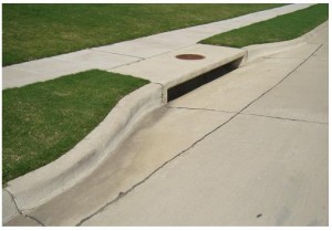 The types of pavement drain inlets in common use include curb inlets, gutter inlets and combination inlets. A curb inlet is just an opening in the curb as shown in the image at the
 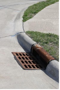 left. A combination inlet has both a curb opening and a grate opening in the bottom of the gutter as shown in the image at the right. Gutter inlets typically have a grate over the opening, while curb inlets are
 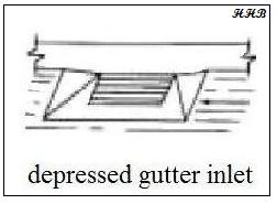 typically open without a grate, as shown in the pictures. A sketch of a depressed gutter inlet is shown at the bottom left.
Curb Inlet Image Credit: Lone Star Manhole and Structures
Combination Inlet Image Credit: Robert Lawton – Wikimedia Commons
Depressed Gutter Inlet Image Credit: H. H. Bengtson
The Weir Model for Sizing Storm Water Drain Inlets
The openings for storm water drains can be modeled as a weir if the opening isn’t completely submerged at the design storm water runoff flow rate. For a curb opening this would be the case if the depth of storm water at the opening is less than the height of the opening. For a gutter opening it would occur if the design flow rate of storm water runoff enters the grate around the edges, without completely submerging the opening.
The equation used to size storm drains with unsubmerged openings is theC sharp crested weir equation: Q = CwLd1.5, where:
- Q = the design storm water runoff rate that must flow through the inlet in cfs for U.S. or m3/s for S.I. units.
- Cw = a weir coefficient, which is a dimensionless constant. Typical values are 2.3 for U.S. units and 1.27 for S.I. units.
- L = the length of the curb opening (or the length of the the gutter opening in the direction of the storm water flow), in ft for U.S. or m for S.I. units.
- d = the depth of storm water above the bottom of the curb opening or its depth above the gutter inlet opening in ft for U.S. or m for S.I. units.
The Orifice Model for Sizing Storm Water Drain Inlets
The storm water drain opening can be modeled as an orifice if it will be completely submerged at design flow of storm water runoff. This would be the case for a curb opening if the water depth is more than the height of the curb opening at design storm water flow. A gutter opening could be modeled as a weir if the gutter opening is completely submerged at the design storm water runoff rate. The equation used for sizing storm water inlets with the orifice model is:
Q = Co A(2gde)1/2 , where:
- Q = the design storm water runoff rate that must flow through the inlet in cfs for U.S. or m3/s for S.I. units.
- Co = the orifice coefficient, which is dimensionless. The value typically used for storm water inlet design is 0.67.
- A = the area of the inlet opening in ft2 for U.S. or m2 for S.I. units.
- g = the acceleration due to gravity (32.2 ft/sec2 for U.S. or 9.82 m/s2 for S.I units).
- de = the height of storm water above the centroid of the opening in ft for U.S. or m for S.I. units.
Note that de = d – h/2, for a curb opening, where d is the depth of storm water above the bottom of the opening and h is the height of the curb opening. For a gutter opening, de = d, where d is the height of storm water above the gutter opening at design storm water flow.
An Excel Spreadsheet as a Storm Water Drain Inlet Design Calculator
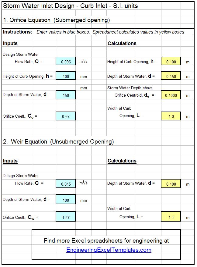
The Excel spreadsheet template shown below can be used to calculate the required size of a curb inlet for storm water drainage, based on specified information about the design storm water runoff rate, height of the curb opening, and the height of the storm water above the bottom of the opening. Why bother to make these calculations by hand? This Excel spreadsheet and others with similar calculations for a gutter opening are available in either U.S. or S.I. units at a very low cost in our spreadsheet store.
References:
1. McCuen, Richard H., Hydrologic Analysis and Design, 2nd Ed, Upper Saddle River, NJ, 1998.
2. ASCE. 1992. Design and Construction of Urban Stormwater Management Systems. The Urban Water Resources Research Council of the American Society of Civil Engineers (ASCE) and the Water Environment Federation. American Society of Civil Engineers, New York, NY.
3. Texas Department of Transportation/Online Hydraulic Design Manual/Storm Drain Inlets.

