Partially Contracted V-Notch Weir Excel Spreadsheets

Where to Find a Partially Contracted V-Notch Weir Excel Spreadsheet

To obtain a Partially Contracted V-notch weir Excel spreadsheet for , click here to visit our spreadsheet store. Why use online calculators or hand calculations when you can buy a partially contracted V-notch weir spreadsheet for only $11.95.  Read on for information about Excel spreadsheets that can be used as v-notch weir open channel flow calculators for partially contracted flow.

For background on fully contracted v notch weir calculations, see the article, “V-Notch Weir Calculator Excel Spreadsheet.”   That article gives general information about V notch weirs and equations and conditions required for fully contracted v notch weir calculations.

Partially Contracted V Notch Weir Calculations for a 90o Notch Angle

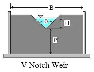
Partially contracted v-notch weir excel spreadsheet diagram

The equation shown below is recommended by the U.S. Dept. of the Interior, Bureau of Reclamation in their Water Measurement Manual (ref #1 below) for calculations with a partially contracted, 90o, v notch, sharp crested weir with free flow conditions and 0.4 ft < H < 2 ft (0.05 m < H < 0.38 m).

In U. S. units:  Q = 4.28H2.48, where Q is discharge in cfs and H is head over the weir in ft.

In S.I. units:  Q = 1.36H2.48, where Q is discharge in  m3/s and H is head over the weir in m.

The conditions for the v notch weir to be fully contracted are:

H/P < 1.2,    H/B < 0.4,    P > 0.33 ft (0.1 m),   B > 2 ft (0.6 m)

The diagram above shows the parameters H, P, θ and B for a v notch weir as used for open channel flow rate measurement in a partially contracted v-notch weir excel spreadsheet.

Screenshot of a Partially Contracted V Notch Weir Excel Spreadsheet

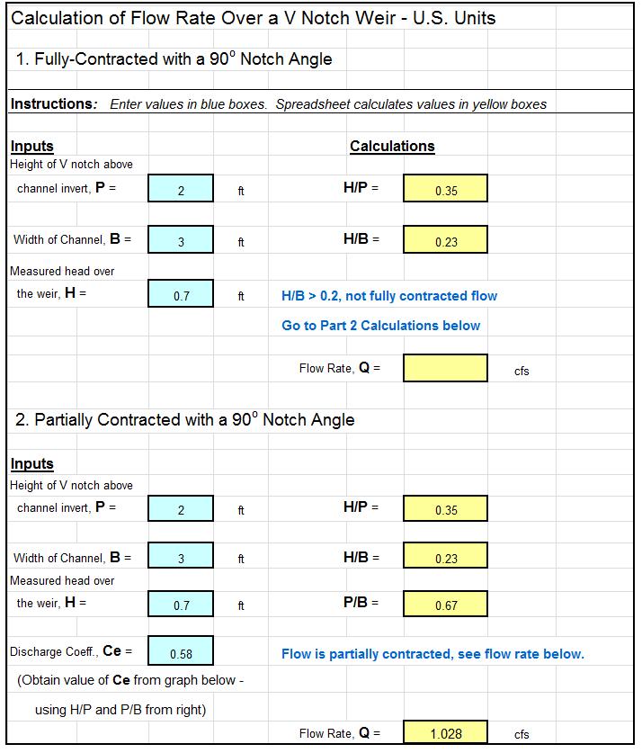
The screenshot below shows a partially contracted v notch weir excel spreadsheet for making 90o, partially contracted v-notch weir calculations in U.S. units.  Based on specified values for H, P, & B (and a value for Ce from a graph on the spreadsheet), the spreadsheet checks on whether the required conditions for partially contracted flow are met and then calculates the flow rate, Q.  This Excel spreadsheet and others for v notch weir calculations are available in either U.S. or S.I. units at a very low cost (only $11.95)  in our spreadsheet store.

partially contracted v-notch weir spreadsheet screenshot

References:

1. U.S. Dept. of the Interior, Bureau of Reclamation, 2001 revised, 1997 third edition, Water Measurement Manual, available for online use or download at: http://www.usbr.gov/pmts/hydraulics_lab/pubs/wmm/index.htm.

2. Bengtson, Harlan H., “Sharp Crested Weirs for Open Channel Flow Measurement,” an Amazon Kindle ebook

3. Bengtson, Harlan H., Open Channel Flow III – Sharp Crested Weirs, an online continuing education course for PDH credit, http://www.online-pdh.com/engcourses/course/view.php?id=87

4. Munson, B. R., Young, D. F., & Okiishi, T. H., Fundamentals of Fluid Mechanics, 4th Ed., New York: John Wiley and Sons, Inc, 2002.

Proportional Sutro Weir Design Calculation Excel Spreadsheet

Where to get a Proportional Sutro Weir Design Calculation Excel Spreadsheet

For a proportional sutro weir design calculation Excel spreadsheet in either U.S. or S.I. units, click here to visit our spreadsheet store.  Obtain convenient, easy to use spreadsheets for proportional sutro weir design calculations at reasonable prices. Read on for information about the use of a proportional sutro weir design calculation Excel spreadsheet.

Principles of a Proportional Sutro Weir Design Calculation Excel Spreadsheet

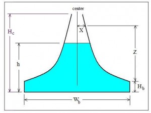
For the commonly used rectangular weir or V-notch weir, the flow rate over the weir Diagram for proportional sutro weir design calculation excel spreadsheetincreases as the head over the weir increases, but the flow rate increases at a faster rate than the head over the weir.  For some applications, it is desirable for the flow rate over a weir to be proportional to the head over the weir.  The sutro weir, also known as a proportional weir accomplishes this by having the width of the opening above the weir crest decrease with increasing head over the weir crest as shown in the diagram of a sutro weir at the right.  Equations that can be used for proportional sutro weir design are discussed in the next section.

Equations for Proportional Sutro Weir Design Calculation Excel Spreadsheet

Equations for the base width and base height of a sutro weir are as follows:

base height equation for proportional sutro weir design calculation Excel spreadsheet

base width equation for proportional sutro weir design calculation Excel spreadsheet

  • Wb  =  base width in ft (m for S.I. units)
  • Hb  =  base height in ft (m for S.I. units)
  • Hc  =  max height or curved portion of weir in ft (m for S.I. units)
  • Qmax  =  design maximum flow over the weir in cfs (m3/s for S.I. units)
  • Qmin  =  design minimum flow over the weir in cfs (m3/s for S.I. units)
  • g = acceleration of gravity = 32.17 ft/s/s (9.81 m/s/s for S.I. units)

The equation for the curved portion of a proportional sutro weir is:

Curve Equation for proportional sutro weir design calculation Excel spreadsheet

X and Z are position parameters as shown in the diagram above.  They will have the same units as Wb .

A Screenshot for a Proportional Sutro Weir Design Calculation Excel Spreadsheet

For a proportional sutro weir design calculation Excel spreadsheet with calculations in S.I. or U.S. units, or for other spreadsheets for open channel flow measurement calculations, see: www.engineeringexceltemplates.com

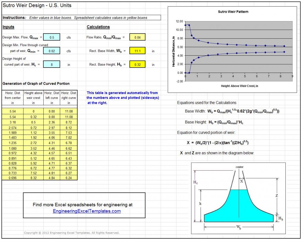
The Excel spreadsheet screenshot below shows part of a spreadsheet for proportional sutro weir design calculations, available  at our spreadsheet store in either U.S. or S.I. units at a very reasonable price.

 Screenshot of Proportional Sutro Weir Design Calculation Excel Spreadsheet

Reference

1, U.S. DOT, Fed Highway Admin, Urban Design Manual, Circular No. 22, 2nd Ed. 2001  (Publ. No. FHWA-NHI-010021-HEC-22)

2. Bengtson, Harlan H., Proportional Weir Design Equations,” an online blog article

Wastewater Lagoon Design Spreadsheets

Where to get Wastewater Lagoon Design Spreadsheets

For wastewater lagoon design spreadsheets in either U.S. or S.I. units, click here to visit our spreadsheet store.  Obtain convenient, easy to use spreadsheets for wastewater lagoon design calculations at reasonable prices. Read on for information about the use of Excel spreadsheets for wastewater lagoon design.  Three types of wastewater lagoons that will be discussed next are the anaerobic lagoon, the facultative lagoon, and the maturation pond.

Anaerobic Wastewater Lagoon Design

Anaerobic lagoons are most useful for incoming wastewater with a high BOD content.  If present, an anaerobic lagoon would typically be the first type of treatment, often followed by facultative and or maturation ponds.  Anaerobic lagoons are deeper than facultative or maturation ponds, usually 8 to 15 ft.  Anaerobic wastewater lagoon Design is usually based on volumetric loading (kg BOD/day/m3 or  lb BOD/day/1000 ft3).  A specified minimum hydraulic retention time may also be used.

Facultative Wastewater Lagoon Design

The classic type wastewater treatment lagoon is the facultative pond.  It is aerobic at the  top with an anaerobic sediment layer at the bottom.  Algae growing in the lagoon are important for maintaining dissolved oxygen in the pond.  There are often one or more primary facultative ponds and one or more secondary ponds.  A typical three cell layout for two primary cells and one secondary cell is shown in the diagram below.  A well designed and operated facultative lagoon system can provide secondary level treatment if algae are removed from the effluent.  Facultative wastewater lagoon design is typically based on surface loading (kg BOD/day/ha or lb BOD/day/acre).  A specified minimum hydraulic detention time is often used as a design factor also.Wastewater Lagoon Design - Three Cell Layout

Maturation Wastewater Lagoon Design

A maturation pond will typically be the last type of pond in a wastewater lagoon system if it is present.  There is usually little additional BOD removal in a maturation pond.  Its primary function is disinfection/reduction in bacterial content.  Maturation pond design is often based on required reduction in coliform bacteria with perhaps a minimum hydraulic retention time.

A Screenshot for a Wastewater Lagoon Design Spreadsheet

For a wastewater lagoon design spreadsheet with calculations in S.I. or U.S. units, or for other spreadsheets for activated sludge wastewater treatment calculations, see: www.engineeringexceltemplates.com

The Excel spreadsheet screenshot below shows part of a spreadsheet for wastewater lagoon design calculations, available  at our spreadsheet store in either U.S. or S.I. units at a very reasonable price.

Screenshot of wastewater lagoon design spreadsheet

References

1.  USEPA, Principles of Design and Operations of Wastewater Treatment Pond Systems for Plant Operators, Engineers, and Managers, EPA/600/R-11/088, August 2011.

2. Mara, D. & Pearson, H., Design Manual for Waste Stabilization Ponds in Mediterranean Countries, Lagoon Technology International Ltd, 1998.