MBBR Wastewater Treatment Design Spreadsheet for BOD Removal

Where to Find an MBBR Wastewater Treatment Design Spreadsheet

To obtain an MBBR wastewater treatment design spreadsheetclick here to visit our spreadsheet store.  This Excel spreadsheet can be used for MBBR process design calculations. You can buy a convenient MBBR wastewater treatment design spreadsheet  for a very reasonable price.  This spreadsheet makes MBBR process design calculations for several configurations for BOD removal and for nitrification.  It is available in either U.S. or S.I. units.  Read on for information about using an MBBR Wastewater Treatment Design spreadsheet.

Background for MBBR Wastewater Treatment Design Spreadsheet

The moving bed biofilm reactor (MBBR) is a relatively recently developed wastewater treatment process.  It was developed in the 1990’s, but is now in use in many countries around the world.

The MBBR wastewater treatment process is quite flexible.  It is used for domestic and industrial wastewater treatment and can be designed for BOD removal alone or in combination with nitrification.  It is used as a single stage process or as a two-stage or three-stage process.

 Example MBBR Wastewater Treatment Design Spreadsheet

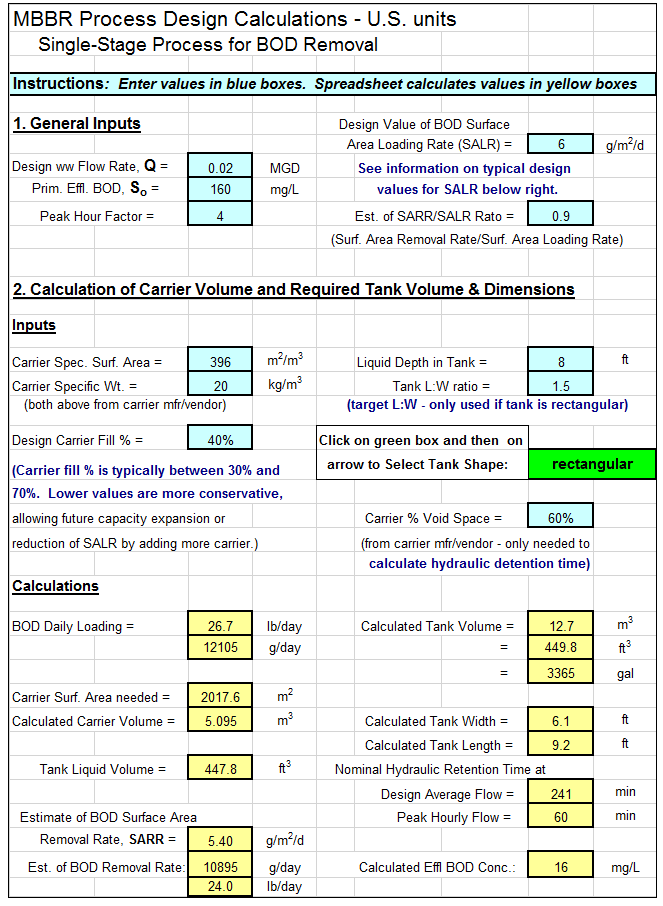
An example MBBR wastewater treatment design spreadsheet is partially shown in the image below.  This Excel spreadsheet can be used to calculate the required MBBR tank volume and dimensions, based on user input media information and wastewater design flow and characteristics.  This Excel spreadsheet, as well as others for wastewater treatment process design calculations, is available in either U.S. or S.I. units for a very reasonable price in our spreadsheet store.

MBBR Wastewater Treatment Design Spreadsheet

 References:

1. McQuarrie, J.P. and Boltz, J.P., Moving Bed Biofilm Reactor Technology: Process Design and Performance, Water Environment Research, Vol 83, No 6, June 2011.

2. Bengtson, Harlan, “MBBR Process Design Calculations Spreadsheet,” an online blog article

3. Bengtson, Harlan H,, “Spreadsheets for MBBR Process Design Calculations“, Available as an Amazon Kindle e-book and as a paperback.

4. Bengtson, Harlan H., “Biological Wastewater Treatment Process Design Calculations,” available as an Amazon Kindle e-book or as a paperback.

5. Bengtson, Harlan H. “MBBR Wastewater Treatment Processes“, an online course for PDH engineering continuing education credit.

Flow Through Non Circular Ducts Spreadsheet

Where to Find a Spreadsheet for Flow Through Non Circular Ducts

To obtain a spreadsheet for  flow through non circular ductsclick here to visit our spreadsheet store.  Intended for use in calculating flow rate or frictional head loss and frictional pressure drop, you can buy a convenient spreadsheet for  flow through non circular ducts calculations for a very reasonable price.  This spreadsheet makes calculations with the Hagen Poiseuille equation for laminar flow and with the Moody friction factor and the Darcy Weisbach equation for turbulent flow for flow through an annulus and for flow through a rectangular duct.  Turbulent flow calculations can be made for a general non-circular duct with known cross-sectional area and wetted perimeter.  It is available in either U.S. or S.I. units.  Read on for information about a spreadsheet for flow through a non circular duct calculations.

Turbulent Flow Through Non Circular Ducts

The Moody friction factor is used in the Darcy Weisbach equation for turbulent flow through non circular ducts.  The Darcy Weisbach equation is:

Flow Through Non Circular Ducts Equation

Where the hydraulic diameter is used for D in the Darcy Weisbach equation for flow through non circular ducts.  For further discussion of the Moody friction factor and its use in the Darcy Weisbach equation for pipe flow calculations, see the post, “Pipe Flow-Friction Factor Calculations with Excel Spreadsheets.”

Laminar Flow Through Non Circular Ducts

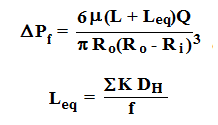
For laminar flow in an annulus or laminar flow in a rectangular duct, the Hagen Poiseuille equation should be used.  For flow through an annulus, it is:

Flow Through Non Circular Ducts Laminar Equations

Hagen Poiseiulle equations for laminar flow through an annulus


 Example Spreadsheet for Flow Through Non Circular Ducts

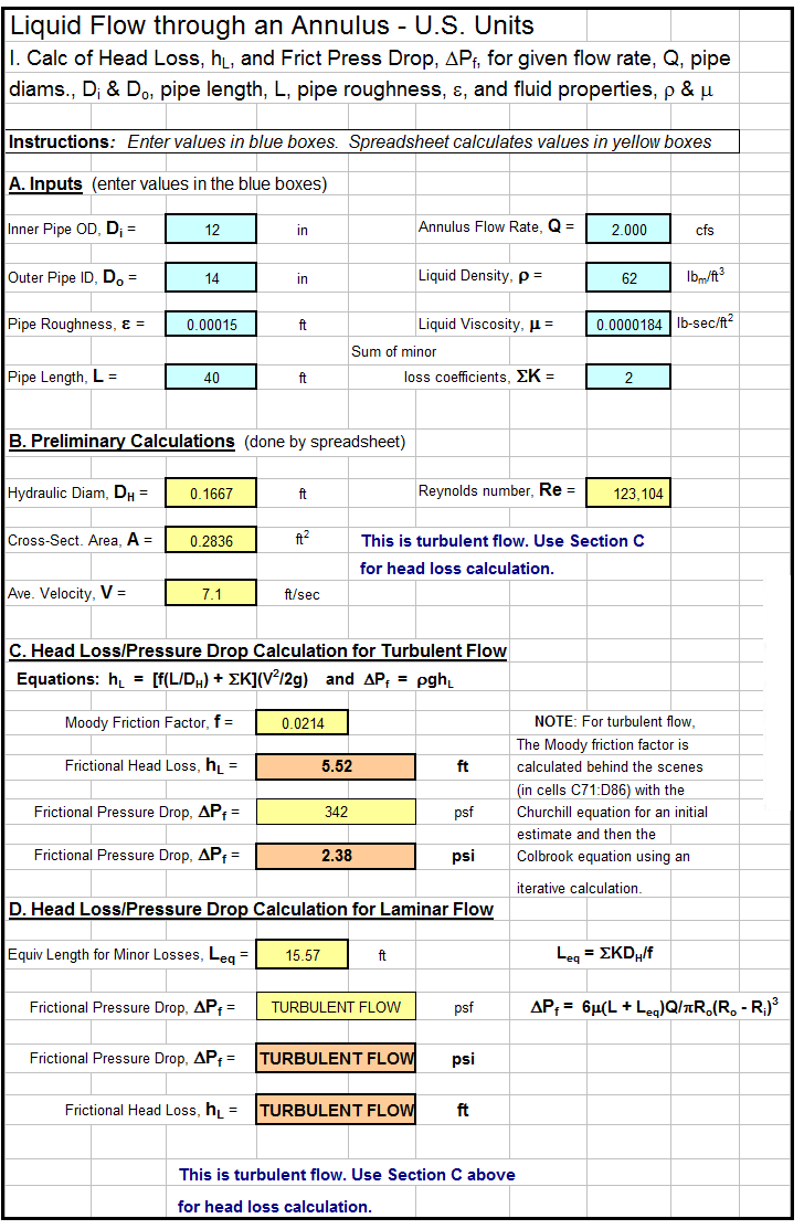
A spreadsheet for flow through non circular ducts calculations is partially shown in the image below.  This Excel spreadsheet can be used to calculate the frictional pressure drop and head loss or flow rate for flow through an annulus (laminar or turbulent flow), flow through a rectangular duct (laminar or turbulent flow) or flow through a general non circular duct (turbulent flow only).  This Excel spreadsheet, as well as others for pipe flow calculations, is available in either U.S. or S.I. units for a very reasonable price in our spreadsheet store.

Flow Through Non Circular Ducts - Annulus

 Reference:

1. Bengtson, Harlan, “Pressure Drop in a Non Circular Duct”, an online blog article

Hydraulic Grade Line – Energy Grade Line Calculator Spreadsheet

Where to Find a Hydraulic Grade Line – Energy Grade Line Calculator Spreadsheet

To obtain a  hydraulic grade line – energy grade line calculator spreadsheet for calculating and plotting HGL and EGL, click here to visit our spreadsheet store.  Intended for use in calculating and plotting HGL and EGL for up to 10 points of stormwater flow along a storm sewer line, you can buy a convenient spreadsheet to make HGL and EGL calculations and plots for a very reasonable price.  This spreadsheet is available in either U.S. or S.I. units.  Read on for information about a storm sewer hydraulic grade line – energy grade line calculator spreadsheet.

Equations for Hydraulic Grade Line and Energy Grade Line

The equations for the Hydraulic Grade Line and Energy Grade Line (EGL) are:

Hydraulic Grade Line - Energy Grade Line Calculator equationsWhere:    HGL

HGL = hydraulic grade line in ft                EGL = energy grade line in ft

P = pressure in psf                                        γ = specific weight in lb/ft3

h = elevation in ft                                         V = velocity in ft/sec

g = acceleration of gravity in ft/sec2

Example Spreadsheet for Hydraulic Grade Line – Energy Grade Line Calculator Plots

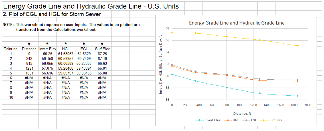
A screenshot for a Hydraulic Grade Line – Energy Grade Line calculator  spreadsheet is partially shown in the image below.  This Excel spreadsheet can be used to calculate and plot the energy grade line and hydraulic grade line.  This Excel spreadsheet, as well as others for stormwater management calculations, is available in either U.S. or S.I. units for a very reasonable price in our spreadsheet store.

hydraulic grade line - energy grade line calculator plot

Reference:

Bengtson, Harlan H., Hydraulic Grade Line Calculation Spreadsheet, an informational blog article

Trilateration Surveying Data Processing

Where to Find a Trilateration Surveying Data Processing Program

To obtain a  trilateration surveying data processing program click here to visit our download store.  Look for “WinTri – A Computer Program for Trilateration” in the “Surveying” category to find it.  This standalone program can be used for data reduction in connection with trilateration surveys.  You can buy this convenient data reduction program for trilateration surveys for a very reasonable price (only $79.95).

Introduction to WinTri – A Trilateration Surveying Data Processing Program

WinTri is a standalone computer program (not a spreadsheet) for trilateration surveying data processing.  It can be used for reduction of data from trilateration surveys; in particular WinTri calculates the coordinates of stations.  The program is general in that it will handle any surveying control figure that a user might specify.  Data validation is a key feature of the program.  Input data from surveys are extensively checked for errors, and warning messages are displayed on the screen when an error is encountered.  In calculating results, WinTri employs least-squares adjustment.

Win-Tri Help screens provide complete, annotated examples of all required input files.  Sufficient explanation is given so that someone who has never used the program before can prepare all input data solely by studying the Help screens.

How to Use WinTri – A Trilateration Surveying Data Processing Program

This trilateration surveying data processing program is simple to use.  Aside from Help screens, the program displays only three screens.  The first screen is the title screen, and the second is a screen with a single message directing the first-time user to the appropriate help screen designed for beginners.  The third screen displays seven command buttons: (1) Read master file, (2) Enter elevations, (3) Save elevations, (4) Read raw data, (5) Calculate coordinates (of stations), (6) Save results, and (7) Re-start.  The buttons are enabled and disabled automatically as the program user proceeds through the various steps of the analysis.  The “Save elevations” button allows the user to interrupt hand entry of elevation data, stop the program and subsequently start the program at a later time without having to re-enter those elevations that had already been entered.

Besides the command buttons, the third screen contains a textbox labeled “Program Log.”  If a step in the operation of the program is successfully completed, the program log displays a message to that effect.  If an error occurs, then the log displays a message describing the error.

A Screenshot of WinTri – A Trilateration Surveying Data Processing Program

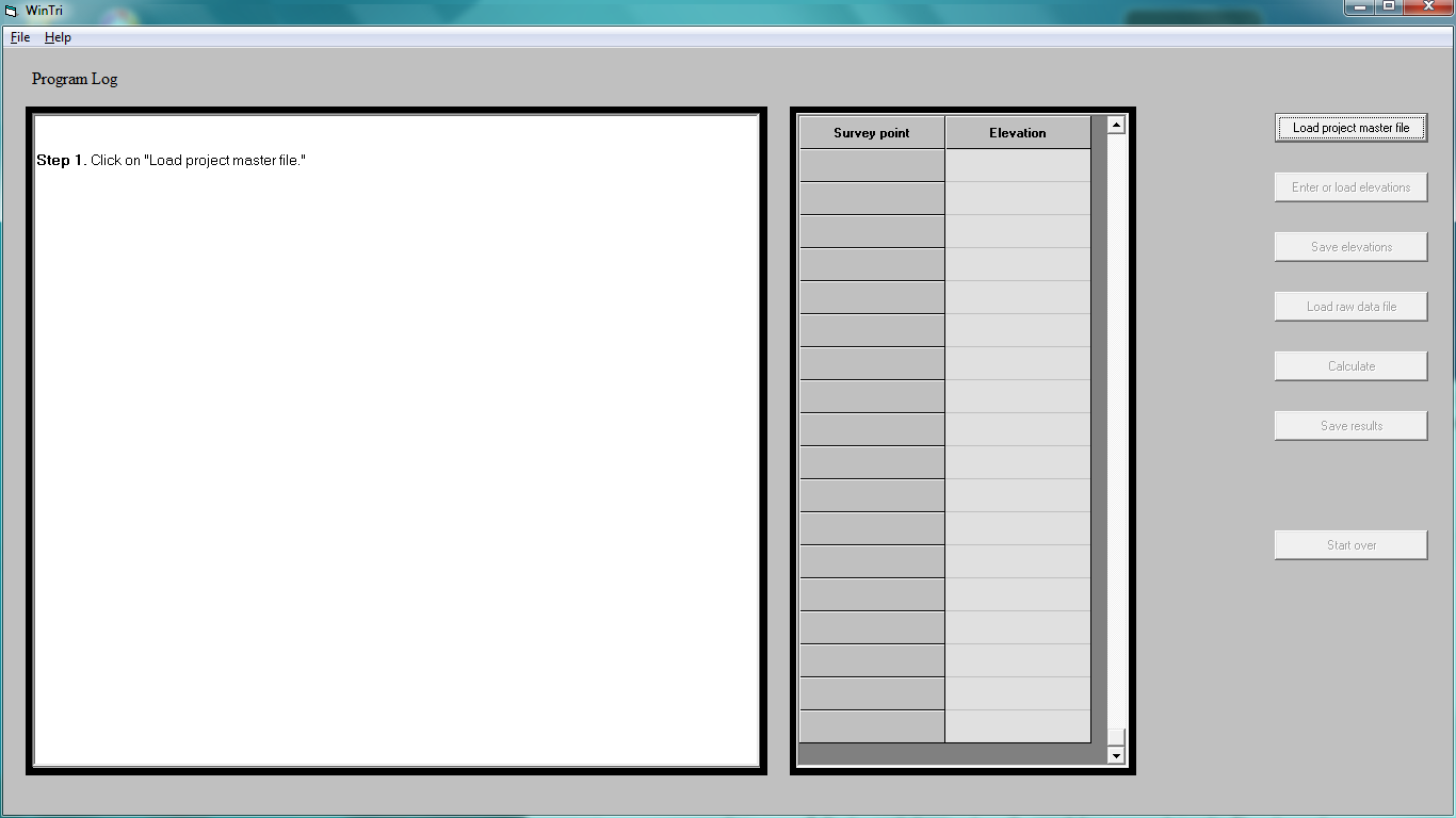
The image below shows a screenshot of the introductory screen of WinTri a trilateration surveying data processing program.

WinTri Trilateration Surveying Data Processing Program Screenshot

Figure 1. Screenshot of WinTri, a Trilateration Surveying Data Processing Program

The Source Code for WinTri – A Trilateration Surveying Data Processing Program

In addition to an executable module that can be installed and run, the source code, consisting of about 5000 Visual Basic 6.0 statements is provided in case the user wants to revise the program to meet specialized needs.  The program is thoroughly documented with commen” are used throughout so that much of the code reads like ordinary English.

Anyone involved in trilateration surveys should find the program helpful.  It is easy to learn, it can be used for any control network that the user specifies, and – most important of all – it greatly lessens the tedious and time-consuming task of locating and identifying errors in the survey data.

Reference

Rossow, Mark, Trilateration Surveying Data Processing, An informational blog article.

How to Draw V and M Diagrams – A Tutorial

Where to Find a Tutorial on How to Draw V and M Diagrams

To obtain a tutorial program on  how to draw V and M diagramsclick here to visit our download store.  Look for “Understanding V and M Diagrams” in the “Strength of Materials” category to find it.  This standalone program provides practice for learning the principles underlying shear diagrams and bending moment diagrams.  You can buy this convenient tutorial beam diagrams program on how to draw shear and bending moment diagrams for a very reasonable price (only $4.95).

A Description of the Tutorial Program on How to Draw V and M Diagrams

This standalone program contains over 50 exercises, which have been chosen to represent all common boundary conditions and load cases for structural beams.  The difficulty of the exercises ranges from easy to challenging.

The program is highly interactive: starting with a point at the origin of the shear diagram, the user calculates the coordinates of the next point where the diagram changes slope or direction.  Then the user employs the mouse cursor to plot this point on the screen.  After plotting the point, the user specifies the type of curve (for example, straight line or curved line concave up), connecting the two points.  The user proceeds in a similar manner to plot the next point on the diagram and connect it to the most recently plotted point.  Continuing in this fashion, the user completes the shear diagram and then goes on to the bending moment diagram.

Five kinds of Help screens are available:

  • A step-by-step tutorial on how to operate the program is provided which guides the user through a simple example on how to draw V and M diagrams.
  • Diagrams defining sign conventions for V (shear) and M (bending moment) are given.
  • Techniques for calculating V and M are described in terms of specific numerical calculations.
  • The answer for the current step in the diagram construction is given—the value of V or M or type of curve connecting two points on the diagram.  How the answer is calculated is explained in detail.
  • A complete numerical example showing both shear and bending moment diagrams with key values labeled on the diagrams is provided.  When the user positions the mouse cursor over any part of the diagram, a pop-up window opens containing an explanation of how that particular part of the diagram was constructed.  For example, positioning the cursor over the point of maximum moment on the beam (which is loaded with a distributed load) brings up the comment that the maximum moment occurs where the shear is zero.  Positioning the cursor over a jump in the shear diagram brings up the comment that the jump is caused by the support reaction acting on the beam.

A quiz facility is also provided for use of the program in a classroom setting.

Screenshot of Tutorial Program on How to Draw V and M Diagrams

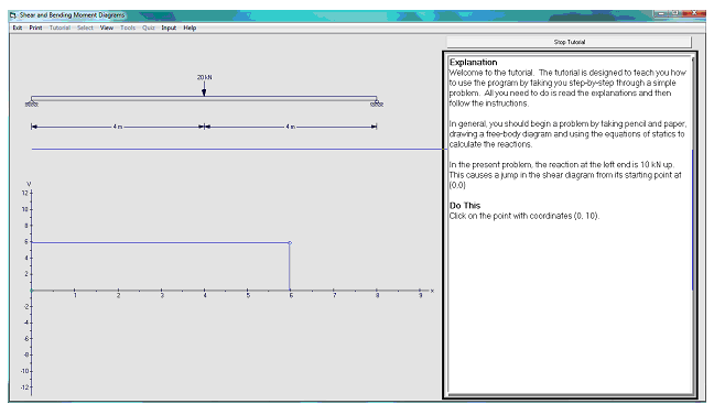
The beginning of the tutorial on How to Draw V and M Diagrams is shown in the image below.  This program can be used to help understand shear and bending moment diagrams and how to construct them.

How to Draw V and M Diagrams Tutorial Screenshot

Figure 1. A Tutorial Program on How to Draw V and M Diagrams

Reference

Rossow, M., Shear and Bending Moment Diagrams – A Tutorial, a blog article at: http://www.engineeringexceltemplates.com/blog.aspx

Spreadsheets for Turbulent and Laminar Flow in Pipes

Where to Find a Spreadsheet for Turbulent and Laminar Flow in Pipes

To obtain a spreadsheet for  Turbulent and Laminar flow in pipesclick here to visit our spreadsheet store.  Intended for use in calculating pipe flow rate, frictional head loss, or required pipe diameter, you can buy a convenient spreadsheet for turbulent or laminar flow in pipes calculations for a very reasonable price.  This spreadsheet makes calculations with the Hagen Poiseuille equation for laminar flow and with the Moody friction factor and the Darcy Weisbach equation for turbulent flow.  It is available in either U.S. or S.I. units.  Read on for information about a spreadsheet for turbulent and laminar flow in pipes calculations.

The Reynolds Number Criterion for Turbulent and Laminar Flow in Pipes

For flow in pipes, the Reynolds number is:  Re  =  DVρ/μ, for any consistent set of units for pipe diameter, D, flow velocity, V, fluid density, ρ, and fluid viscosity, μ.  Pipe flow will be turbulent if the Reynolds number is greater than 4000 and will be laminar if the Reynolds number for the flow is less than 2300.  If the Reynolds number is between 2300 and 4000, the flow may be either laminar or turbulent, depending on factors such as the type of pipe entrance and the roughness of the pipe wall.

Equations for Turbulent and Laminar Flow in Pipes

For discussion of the Moody friction factor and its use in the Darcy Weisbach equation for turbulent pipe flow calculations, see the post, “Pipe Flow-Friction Factor Calculations with Excel Spreadsheets.”  For laminar flow in pipes, the Hagen Poiseuille equation is as follows:             ΔP  =  8μLQ/(Πr4 ),  where  ΔP is the frictional pressure drop in lb/ft2, μ is the fluid viscosity in lb/ft-sec, L is the length of the pipe in ft, Q is the flow rate through the pipe in cfs, and r is the pipe radius in ft.  Note that the Hagen Poiseulle equation is identical with the Darcy Weisbach equation for pipe flow with the Moody friction factor equal to 64/Re.

 Example Spreadsheet for Turbulent and Laminar Flow in Pipes Calculations

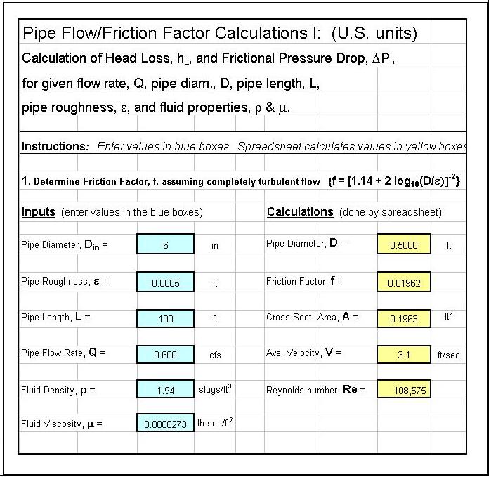
A spreadsheet for Turbulent and Laminar Flow in Pipes calculations is partially shown in the image below.  This Excel spreadsheet can be used to calculate the frictional pressure drop and head loss for known pipe flow rate, diameter and length along with fluid density and viscosity and the pipe wall roughness.  It can also be used to calculate pipe flow rate or minimum required pipe diameter if the other parameters are known.  This Excel spreadsheet, as well as others for pipe flow calculations, is available in either U.S. or S.I. units for a very reasonable price in our spreadsheet store.

References

1.  Munson, B. R., Young, D. F., & Okiishi, T. H., Fundamentals of Fluid Mechanics, 4th Ed., New York: John Wiley and Sons, Inc, 2002.

2. Darcy Weisbach equation history – http://biosystems.okstate.edu/darcy/DarcyWeisbach/Darcy-WeisbachHistory.htm

3. Bengtson, Harlan H.  Pipe Flow Calculations with the Darcy Weisbach Equation,  An online blog article.

4. Bengtson, H.H., Pipe Flow/Friction Factor Calculations with Excel, an online continuing education course for Professional Engineers.

5. Bengtson, Harlan, “Advantages of Spreadsheets for Pipe Flow/Friction Factor Calculations“, An Amazon Kindle e-book.

Natural Gas Pipeline Flow Calculation Spreadsheet

Where to Find a Natural Gas Pipeline Flow Calculation Spreadsheet

To obtain a natural gas pipeline flow calculation spreadsheet , click here to visit our spreadsheet store.  Intended for use in making natural gas pipeline design calculations, you can buy a convenient natural gas pipeline flow calculation spreadsheet for a very reasonable price.  This spreadsheet makes calculations with the Weymouth equation, the Panhandle A equation, and the Panhandle B equation, and is available in either U.S. or S.I. units.  Read on for information about a natural gas pipeline flow calculation spreadsheet.

Choice of Equations for Natural Gas Pipeline Flow Calculations

Several different equations are used for natural gas pipeline flow calculations.  If the pressure drop across the pipe is less than 40 % of the average pipeline pressure, then the Darcy Weisbach equation is a possibility.  For longer pipelines with larger pressure drop, the three equations that are in most common use are the Weymouth equation, the Panhandle A equation, and the Panhandle B equation.  The choice among these three equations depends upon the pipeline diameter, the pipe length, and the average pipeline pressure.

The Weymouth Equation for Natural Gas Pipeline Flow Calculations

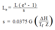
The Weymouth equation was the first of the three to be developed and was the first equation for natural gas pipeline flow calculations that didn’t require an iterative calculation to get a value for the friction factor.  The Weymouth equation is:

Where:

  • Q is the natural gas pipeline flow rate in SCFD
  • E is the pipeline efficiency
  • Tb is the base temperature in oR
  • Pb is the base pressure in psia
  • P1 is the inlet pressure in psia
  • P2 is the outlet pressure in psia
  • G is the specific gravity of the natural gas relative to air
  • Tf is the pipeline temperature of the flowing natural gas in oR
  • L is the pipeline length in miles
  • Le  is the effective pipeline length in  miles
  • ΔH is the height of the pipeline exit above the pipeline inlet in ft
  • Z is the compressibility factor of the natural gas at pipeline T & P
  • D is the pipeline diameter in inches.

Example Spreadsheet for Natural Gas Pipeline Flow Calculations

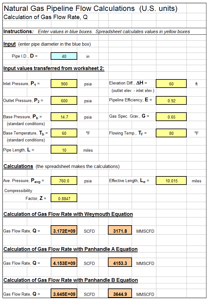
A spreadsheet for Natural Gas Pipeline Flow Calculations is partially shown in the image below.  It can be used to calculate the natural gas pipeline flow rate with the Weymouth equation, the Panhandle A equation and the Panhandle B equation.  This Excel spreadsheet, as well as others for pipe flow calculations, is available in either U.S. or S.I. units for a very reasonable price in our spreadsheet store.

Natural Gas Pipeline Flow Calculation


References for Further Information:

1. Crane Co.,  (1988),  “Flow of Fluids through Valves, Fittings and Pipes,  Technical Paper 401.

2.  GPSA  (Gas Processors Suppliers Association),  (1988),  Engineering Data Book, 11th Ed.

3. Bengtson, Harlan H., (2016), “Natural Gas Pipeline Flow Calculations,”  available as a paperback book or as an Amazon Kindle ebook.

4.  Bengtson, Harlan H.,  (2017),   “Pipe Flow/Friction Factor Calculations with Spreadsheets“,  available as a paperback book or as an Amazon kindle e-book.

5. Bengtson, Harlan H., (2014),  “Natural Gas Pipeline Flow Calculation Spreadsheet“, a blog article at www.EngineeringExcelTemplates.com.


A Spreadsheet for Choked Air Flow Calculation

Where to Find a Spreadsheet for Choked Air Flow Calculation

To obtain a spreadsheet for choked air flow calculations click here to visit our spreadsheet store.  Intended for use in making fanno flow calculations with adiabatic compressible flow of air, you can buy a convenient spreadsheet for choked air flow calculations for a very reasonable price.  This spreadsheet will also calculate the frictional pressure drop, and is available in either U.S. or S.I. units.  Read on for information about a choked air flow calculation spreadsheet for compressible pipe flow.

Conditions for Choked Air Flow Calculation with a Fanno Flow Excel Spreadsheet

For flow of air in a pipe with the frictional pressure drop less than 20% of the inlet air pressure, satisfactory results can be obtained using incompressible flow calculations with the Darcy-Weisbach equation.  For background information on that type of calculation, see the article, “Pipe Flow-Friction Factor Calculations with Excel Spreadsheets.”  If the frictional pressure drop is more than 20% of the incoming air pressure, then Fanno Flow equations should be used, as discussed here using a Fanno Flow Excel spreadsheet.

With adiabatic compressible flow conditions, the maximum air flow rate that can pass through a pipe is that which occurs when the exit Mach number is 1.0.  This is referred to as “choked flow.”

Equations for Choked Air Flow Calculations with a Fanno Flow Excel Spreadsheet

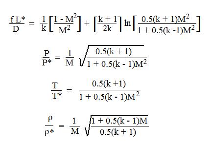
Shown below are the primary equations used in the fanno flow excel spreadsheet being discussed here for compressible flow of air in a pipe.  These equations are for compressible pipe flow with negligible heat transfer with the surroundings, but including effects of friction in the flow.

Fanno Flow Excel Spreadsheet EquationsThe parameters in these fanno flow equations are as follows:

  • f = Moody friction factor
  • L = pipe length
  • D = pipe diameter
  • k = adiabatic constant for the flowing air
  • M = mach number
  • T = air temperature
  • P = air pressure
  • ρ = air density

Parameters with an asterisk refer to conditions at the “choke point” in the pipe, where the Mach number is 1.

Screenshot for a Choked Air Flow Calculation Spreadsheet Using Fanno Flow Equations

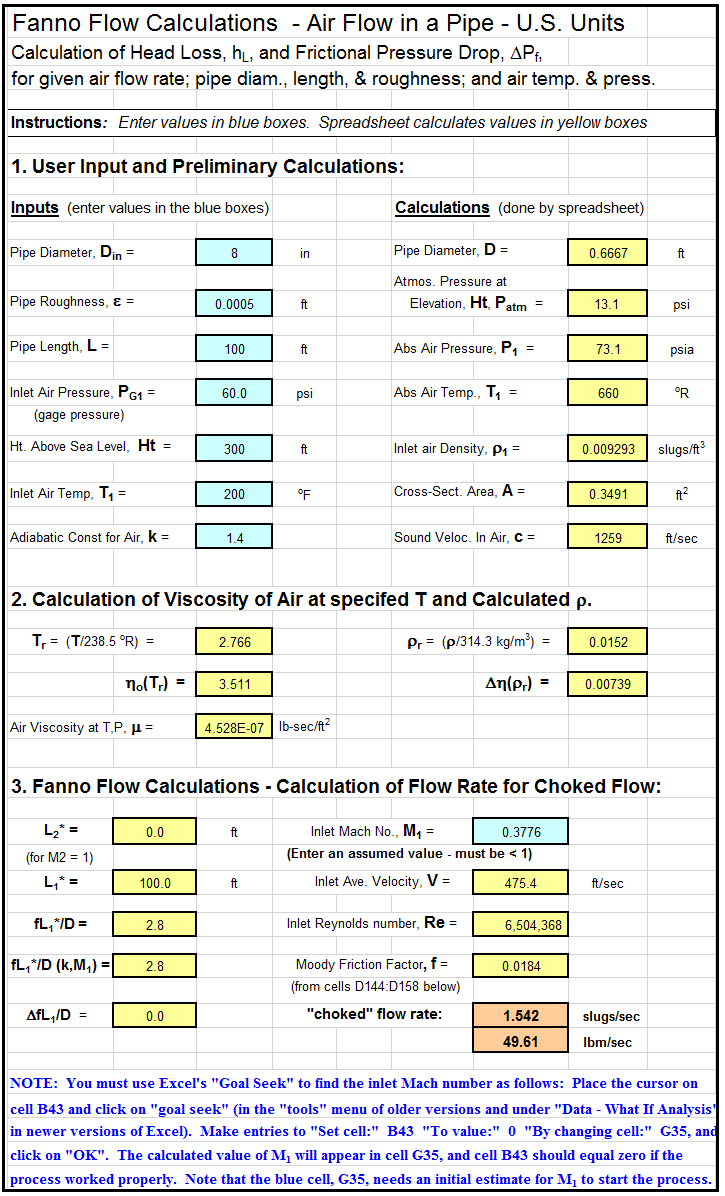
The screenshot below shows part of a fanno flow excel spreadsheet for making compressible air flow calculations.  These calculations are for air flow in a pipe, in S.I. units. This Excel spreadsheet and others for compressible pipe flow calculations in a fanno flow excel spreadsheet are available in either U.S. or S.I. units at a very reasonable cost  in our spreadsheet store.Choked Air Flow Calculation Spreadsheet

Reference:

Bengtson, Harlan H.,  “Compressible Flow Pressure Drop Calculator Spreadsheet,” an online blog article

Trickling Filter Design Calculations Spreadsheet

Where to Find a Trickling Filter Design Calculations Spreadsheet using the NRC Formula

To obtain a trickling filter design calculations spreadsheet using the NRC formula, click here to visit our spreadsheet store.  For use in making trickling filter design calculations with the NRC equation, you can buy a convenient trickling filter design calculations spreadsheet for a very reasonable price.  This spreadsheet will use the NRC equations to calculate the trickling filter diameter needed for either a single stage or a two stage system and will calculate the estimated treatment efficiency for a specified trickling filter system, in either U.S. or S.I. units.  Read on for information about a trickling filter design calculation spreadsheet that uses the NRC formula.

Trickling Filter Design Calculations Background

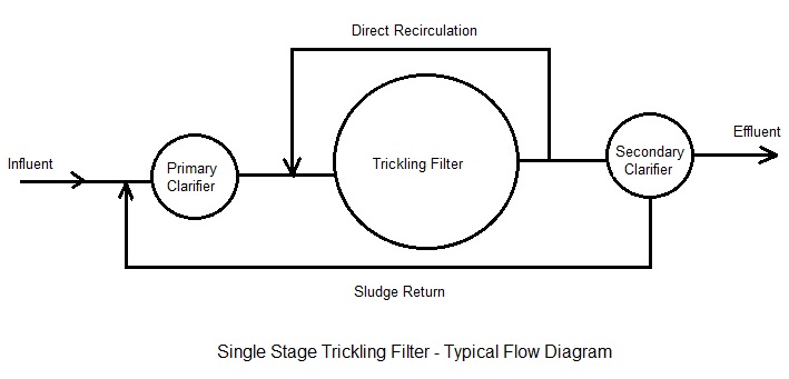
The trickling filter process is widely used for biological wastewater treatment all over the world.  It is an attached growth biological wastewater treatment process.  The aerobic microorganisms grow on a solid medium and the wastewater to be treated flows through the bed.  A flow diagram for a typical single stage trickling filter wastewater treatment plant is shown in the diagram below.  The diagram shows the typical flow pattern through the primary clarifier, trickling filter and secondary clarifier.

trickling filter design calculations spreadsheet flow diagram

Example Trickling Filter Design Calculations Spreadsheet

A trickling filter design calculations spreadsheet  is partially shown in the image below.  It can be used to calculate the trickling filter diameter needed for either a single stage or a two stage trickling filter system using the  NRC formula.  The spreadsheet will also calculate an estimated treatment efficiency for a specified single stage or two stage trickling filter system. This Excel spreadsheet, as well as others for wastewater treatment calculations, is available in either U.S. or S.I. units for a very reasonable price in our spreadsheet store.

Trickling Filter Design Calculations Spreadsheet Screenshot

References for Further Information:

1. Metcalf & Eddy, Inc, (revised by Tchobanoglous, G, Burton, F.L., Stensel, H.D., Wastewater Engineering Treatment and Reuse, 4th Edition, New York, NY, 2003.

2. Vesilind, P.A. and Morgan, S.M., Introduction to Environmental Engineering, 2nd Edition, Belmont, CA, Brooks/Cole, 2004.

3. Bengtson, H. H., “Trickling Filter NRC Equation Spreadsheet“, a blog article at www.EngineeringExcelTemplates.com

A Spreadsheet to Calculate Oxygen Requirement Activated Sludge Process

Where to Find a Spreadsheet to Calculate Oxygen Requirement Activated Sludge Process

To obtain a spreadsheet to calculate oxygen requirement activated sludge processclick here to visit our spreadsheet store.  For use in calculating oxygen requirements and blower specifications, you can buy a convenient spreadsheet to calculate oxygen requirement activated sludge for a very reasonable price.  This spreadsheet will calculate the oxygen requirement and blower specifications for BOD removal or for BOD removal and nitrification for specified wastewater flow and characteristics and diffuser characteristics, in either U.S. or S.I. units.  Read on for information about Excel spreadsheets that can be used to calculate oxygen requirement activated sludge process parameters.

Oxygen Requirement Activated Sludge Background

The theoretical oxygen requirement for BOD removal can be approximated as ranging from  0.90 lb O2/lb BOD removed at an SRT of 5 days to 1.3 lb O2/lb BOD removed at an SRT of 20 days.  This leads to the equation:

O2 requirement in lb/day  =  0.90  +  [(SRT – 5)/(20 – 5)](1.3 – 0.9)(lb/day BOD removed)

A design increase factor (safety factor) is typically multiplied times the calculated oxygen requirement to get the design oxygen transfer rate.  The design oxygen transfer efficiency and the air density at design conditions can then be used to calculate the design air flow rate.  The blower horsepower can then be calculated from the following equation:

Blower hp  =  (Qair)(ΔP)/(229*η)

Where:

  • Qair is the air flow rate in cfm to be delivered by the blower
  • ΔP is the pressure rise across the blower in psi  = outlet pressure – inlet pressure
  • η is the blower efficiency

If oxygen is to be provided for nitrification as well as BOD removal, then additional calculations are needed to estimate the oxygen requirement for nitrification.

Example Spreadsheet to Calculate Oxygen Requirement Activated Sludge Process

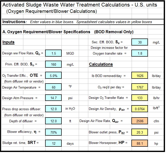
A spreadsheet to Calculate oxygen requirement activated sludge process is partially shown in the image below.  It can be used to calculate the oxygen requirement and blower specifications for an activated sludge wastewater treatment system.  This Excel spreadsheet, as well as others for wastewater treatment calculations, is available in either U.S. or S.I. units for a very reasonable price in our spreadsheet store.

A spreadsheet to calculate oxygen requirement activated sludge process

References:

  1.  Bengtson, Harlan H., “Activated Sludge Oxygen Requirement,”  an online blog article.
  2. Bengtson, Harlan H., “Activated Sludge Calculations Spreadsheet: Aeration Tank Calculations,”  an Amazon Kindle e-book.
  3. Bengtson, Harlan H., “Biological Wastewater Treatment Process Design Calculations,”  available as a paperback book or Amazon Kindle e-book