Forced Convection Heat Transfer Coefficient Calculator

Where to Find a Forced Convection Heat Transfer Coefficient Calculator Spreadsheet

For an Excel spreadsheet to use as a forced convection heat transfer coefficient calculatorclick here to visit our spreadsheet store.  Read on for information about forced convection heat transfer coefficients and their calculation.

An Excel spreadsheet can be a convenient forced convection heat transfer coefficient calculator.   This type of calculation is typically based on a correlation of dimensionless numbers, usually Nusselt number in terms of Reynolds number and Prandtl number.  Forced convection occurs with a fluid moving past a solid surface when the fluid and the solid are at different temperatures.  Newton’s Law of Cooling [ Q = hA(Ts – Tf) ] is a simple expression for the rate for convective heat transfer.  The parameters in Newton’s Law of Cooling are:

  • Q is the rate of forced convection heat transfer (Btu/hr – U.S. or W – S.I.)
  • Ts is the solid temperature (oF – U.S. or oC – S.I.)
  • Tf is the fluid temperature (oF – U.S. or oC – S.I.)
  • A is the area of the surface that is in contact with the fluid (ft2 – U.S. or m2 – S.I.)
  • h is the convective heat transfer coefficient (Btu/hr-ft2oF – U.S. or W/m2-K – S.I.)

Dimensionless Numbers for a Forced Convection Heat Transfer Coefficient Calculator

Determining a good estimate for the heat transfer coefficient, h, is often the most difficult part of forced convection heat transfer calculations.  The process for estimating the heat transfer coefficient for a particular forced convection application is often through a correlation for Nusselt number (Nu) in terms of Reynolds number (Re) and Prandtl number (Pr).  These three dimensionless numbers are defined in the box below, along with the definitions of the parameters that appear in them.

Forced Convection Heat Transfer Coefficient Calculator Dimensionless Numbers

Nusselt Number Correlations for Turbulent Flow Inside a Pipe

The Dittus Boelter equation, which has been around since 1930 (ref #1) has two forms as follows:

Nuo = 0.023 Re0.8Pr0.4 , for ‘heating’ (temperature of wall > temperature of fluid), and

Nuo = 0.026 Re0.8Pr0.3 , for ‘cooling’ (temperature of wall < temperature of fluid).

Subject to: 0.7 < Pr < 120 ; 10,000 < Re < 160,000; L/D > 10 ( L/D > 50 according to some authors).  It is a rather simple equation to use, but has a fairly narrow range of acceptable values for Re and Pr.
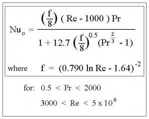
Forced Convection Heat Transfer Coefficient Calculator Nusselt Number CorrelationsAnother correlation (from ref #2) is shown in the box at the right.  The range of values for Re and Pr for this correlation are also shown.  This correlation can be used for a wider range of values of Re and Pr.

A third correlation is shown in the box at the left below.  This correlation, described by Pethukov (ref #3) is only a minor variation of the second correlation shown at the right.  This third correlation works for an even wider range of values for Re and Pr.
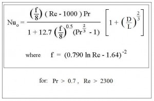
Nusselt Number Correlation for Forced Convection Heat Transfer Coefficient CalculatorExcel spreadsheets can be conveniently used as a forced convection heat transfer coefficient calculator with correlations like these or others for configurations like laminar pipe flow, flow inside a circular annulus, flow outside a cylinder, flow past a bank of tubes, or flow in a noncircular cylinder, because the equations can be programmed into the spreadsheet using Excel formulas.  For free download of an Excel spreadsheet for calculating forced convection heat transfer coefficients for laminar pipe flow, and low cost spreadsheets for all of the other configurations mentioned above,  click here to visit our spreadsheet store.

References

1.  Dittus, P.W. and Boelter, L.M., Univ. Calif. Pub. Eng., Vol. 1, No. 13, pp 443-461 (reprinted in Int. Comm. Heat Mass Transfer, Vol. 12, pp 3-22 (1985).

2.  egr.msu.edu

3.  Petukhov, B.S., “Heat transfer and friction in turbulent pipe flow with variable physical properties,” Adv. Heat Transfer 6, 503-565 (1970).


Hydraulic Radius Open Channel Flow Excel Spreadsheets

Where to Find Spreadsheets for Hydraulic Radius Open Channel Flow Calculations

For an Excel spreadsheet to use for hydraulic radius open channel flow calculations, click here to visit our spreadsheet store.  Read on for information about hydraulic radius open channel flow calculations.

The hydraulic radius is an important parameter for open channel flow calculations with the Manning Equation.  Excel spreadsheets can be set up to conveniently make hydraulic radius open channel flow calculations for flow through common open channel shapes like those for a rectangular, triangular or trapezoidal flume.  Parameters like trapezoid area and perimeter and triangle area and perimeter are needed to calculate the hydraulic radius as described in the rest of this article.

The hydraulic radius for open channel flow is defined to be the cross sectional area of flow divided by the wetted perimeter.  That is: R = A/P, where A is the cross sectional area of flow, P is the portion of the cross sectional perimeter that is wetted by the flow, and R is the hydraulic radius.  The next several sections will present the equations to calculate A, P, and R for some common open channel shapes, and then discuss the use of Excel spreadsheets for hydraulic radius open channel flow calculations.

Hydraulic Radius Open Channel Flow Calculation for Rectangular Channels

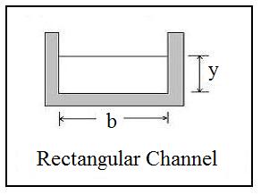
hydraulic radius open channel flow diagram for rectangular channelRectangular channels are widely used for open channel flow, and hydraulic radius open channel flow calculations are quite straightforward for a rectangular cross section. The diagram at the left shows the depth of flow represented by the symbol, y, and the channel bottom width represented by the symbol, b.  It is clear from the diagram that A = by and P = 2y + b.  Thus the equation for the hydraulic radius is: R = by/(2y + b) for open channel flow through a rectangular cross section.


Hydraulic Radius Open Channel Flow Trapezoidal Flume Calculations

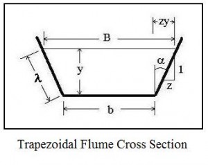
hydraulic radius open channel flow diagram for trapezoidal flumeThe trapezoid is probably the most common shape for open channel flow. Many man-made open channels are trapezoidal flumes, including many urban storm water arroyos in the southwestern U.S.  Also, many natural channels are approximately trapezoidal in cross section. The parameters typically used for the size and shape of a trapezoidal flume in hydraulic radius open channel flow calculations are shown in the diagram at the right. Those parameters, which are used to calculate the trapezoid area and wetted perimeter, are as follows:

  • y is the liquid depth (ft for U.S. & m for S.I.)
  • b is the bottom width of the channel (ft for U.S. & m for S.I.)
  • B is the width of the liquid surface (ft for U.S. & m for S.I.)
  • λ is the wetted length measured along the sloped side (ft for U.S. & m for S.I.)
  • α is the angle of the sloped side from vertical. The side slope also often specified as horiz:vert = z:1.

The common formula for trapezoid area,  A = y(b + B)/2, is a good starting point for obtaining a useful equation for A.  It can be seen from the diagram that B = b + 2zy, so the trapezoid area can be expressed in terms y, b, and z:  A = (y/2)(b + b + 2zy)

Simplifying gives: A = by + zy2.

The wetted perimeter can be expressed as: P = b + 2λ.  The typically unknown sloped length, λ, can be eliminated using the Pythagoras Theorem:

λ2= y2+ (yz)2, or λ = [y2+ (yz)2]1/2 Thus the wetted perimeter is:

P = b + 2y(1 + z2)1/2,   and the hydraulic radius for a trapezoid can be calculated from:

R = (by + zy2)/[b + 2y(1 + z2)1/2]

Hydraulic Radius Open Channel Flow Triangular Flume Calculations

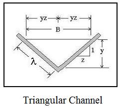
hydraulic radius open channel flow diagram for triangular channelAnother shape used in open channel flow is the triangular flume, as shown in the diagram at the right. The side slope is the same on both sides of the triangle in the diagram.  This is often the case.  The parameters used for hydraulic radius open channel flow calculations with a triangular flume are as follows:

  • B is the surface width of the liquid (ft for U.S. & m for S.I.)
  • λ is the sloped length of the triangle side (ft for U.S. & m for S.I.)
  • y is the liquid depth measured from the vertex of the triangle (ft for U.S. & m for S.I.)
  • z is the side slope specification in the form:  horiz:vert = z:1.

The common formula for triangle area is: A = By/2.  As shown in the figure, however,

B = 2yz, so the triangle area simplifies to: A = y2z.

The wetted perimeter is: P = 2λ , but as with the trapezoidal flume:  λ2= y2+ (yz)2.

This simplifies to the convenient equation: P = 2[y2(1 + z2)]1/2

The hydraulic radius is thus: RH= A/P = y2z/{2[y2(1 + z2)]1/2}

Excel Spreadsheets for Hydraulic Radius Open Channel Flow Calculations

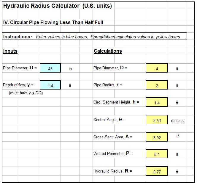
With the equations given in the previous sections, the hydraulic radius can be calculated for a rectangular, triangular or trapezoidal flume if appropriate channel size/shape parameters are known along with the depth of flow.  An Excel spreadsheet like the one shown in the image below, however, can make the the calculations very conveniently.  Excel spreadsheets like the one shown below for use as hydraulic radius open channel flow calculators for rectangular, triangular, and trapezoidal flumes, as well as for partially full pipe flow, are available in our spreadsheet store.

screenshot of hydraulic radius open channel flow Excel spreadsheet

References:

1. Bengtson, Harlan H., Open Channel Flow I – The Manning Equation and Uniform Flow, an online, continuing education course for PDH credit.

2. U.S. Dept. of the Interior, Bureau of Reclamation, 2001 revised, 1997 third edition, Water Measurement Manual.

3. Chow, V. T., Open Channel Hydraulics, New York: McGraw-Hill, 1959.

4. Bengtson, Harlan H., The Manning Equation for Open Channel Flow Calculations,” available as an Amazon Kindle e-book and as a paperback.


Calculate Water Flow Rate for Pipe Sizes with Excel Spreadsheets

Where to Find Excel Spreadsheets to Calculate Water Flow Rate for Pipe Sizes

For Excel spreadsheets to calculate water flow rate for pipe sizes using the Hazen Williams equation, click here to visit our spreadsheet store.  Read on for information about the Hazen Williams equation and its use to calculate water flow rate for pipe sizes.

Excel spreadsheets are very convenient to calculate water flow rate for pipe sizes with the Hazen Williams equation.  Both U.S. and S.I. units will be used in the Hazen Williams spreadsheets and calculations discussed in this article.

Hazen Williams Equation Limitations

The Hazen Williams equation is intended for turbulent water flow rate in pipes at normal ambient temperatures.  The turbulent flow requirement isn’t normally a problem, because most practical transport of water in pipes is turbulent flow.  The Hazen Williams formula works best for water temperature that isn’t too far above or below 60oF.  For calculation of flow rates for pipes with a fluid other than water or for water at a temperature that is far above or far below 60oF, the Darcy Weisbach equation is an alternative to the Hazen Williams equation.  For more information about this alternative, see the post, “Friction Factor/Pipe Flow Calculations with Excel Spreadsheets.”

Forms of the Hazen Williams Equation for Water Flow Rate for Pipe Sizes

The Hazen Williams equation is sometimes expressed as an equation for velocity in the pipe and sometimes as an equation for pipe flow rate.  It also can be expressed in terms of the pipe head loss or the frictional pressure drop.  Finally, the Hazen Williams equation can be written for U.S. or S.I. units.

As an equation for Velocity, the traditional form of the Hazen Williams equation is:

in U.S. units: V = 1.318 C R0.633S0.54, where:

  • V is the water flow velocity, ft/sec
  • C is the Hazen Williams coefficient, dimensionless (depends on pipe material and age)
  • R is the hydraulic radius, ft (R = cross-sectional area of flow/wetted perimeter)
  • S is the slope of the energy grade line, dimensionless (S = head loss/pipe length = hL/L)

in S.I. units:V = 0.85 C R0.633S0.54, where the parameters are as defined above with V in m/s and R in meters.

As an equation for water flow rate for pipe that is circular, the hydraulic radius is R = A/P = (πD2/4)/(πD)  = D/4 and  Q = VA = V(πD2/4).  Substituting these equations into those for velocity give the following for the Hazen Williams equation:

in U.S. units: Q = 193.7 C D2.63S0.54, where:

  • Q is the water flow rate in the pipe, gal/min (gpm)
  • D is the pipe diameter, ft
  • C and S are the same as defined above

in S.I. units: Q = 0.278 C D2.63S0.54, where the parameters are as defined above with Q in m3/s and D in meters.

In terms of frictional pressure drop, ΔP instead of frictional head loss, hL, the Hazen Williams equation is:

in U.S. units: Q = 0.442 C D2.63(ΔP/L)0.54, where

  • Q is the water flow rate in the pipe, gpm,
  • D is the pipe diameter, inches
  • L is the pipe length, ft
  • ΔP is the pressure difference across pipe length L, psi

In S.I. units: Q = (3.763 x 10⁻⁶) C D2.63(ΔP/L)0.54, where

  • Q is the water flow rate in the pipe, m3/hr,
  • D is the pipe diameter, mm
  • L is the pipe length, m
  • ΔP is the pressure difference across pipe length L,  kN/m2


The Hazen Williams Coefficient – C – to Calculate Water Flow Rate for Pipe Sizes

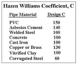
Hazen Williams Coefficients for Water Flow Rate in Pipe CalculationsThe Hazen Williams equation can be used to calculate water flow rates for pipe sizes, only if values of the Hazen Williams coefficient, C, can be obtained for the pipe materials in use. Values of C can be found on internet sites and in handbooks & textbooks. The table at the left shows C values for some commonly used pipe materials.

Source: Toro Ag Irrigation

A Table of Values of Water Flow Rate for Pipe Sizes and Lengths

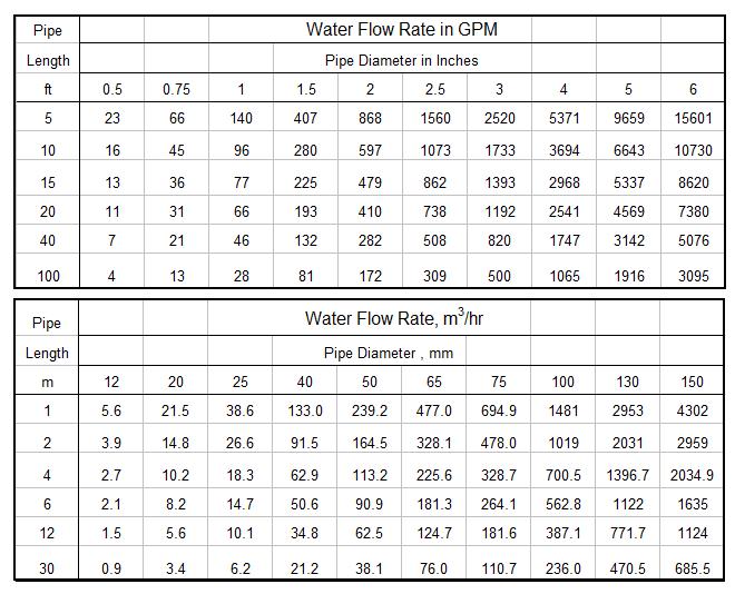
The tables below were prepared using the equations: Q = 0.442 C D2.63(ΔP/L)0.54(U.S.) and  Q = 0.278 C D2.63(ΔP/L)0.54(S.I.) with units as given above, to calculate the water flow rates for PVC pipe with diameters from 1/2 inch to 6 inches (1 mm to 30 mm) and length from 5 ft to 100 ft (12 m to 150 m), all for a pressure difference of 20 psi (140 kn/m2) across the particular length of pipe. The Hazen Williams coefficient was taken to be 150 per the table in the previous section.

Flow Rate for Pipe Sizes and Lengths


Excel Spreadsheets to Calculate Water Flow Rate for Pipe Sizes

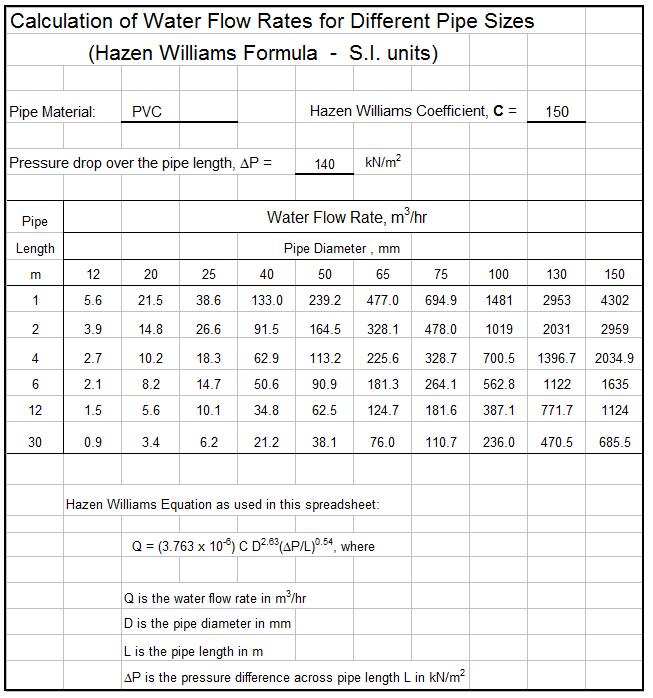
The table shown above can be calculated with an Excel spreadsheet like the one shown below.  It has Excel formulas entered to calculate water flow rates for different pipe sizes using the Hazen Williams equation.  This spreadsheet allows for entering the Hazen Williams coefficient for the proper pipe material, the pressure drop, and the pipe diameter(s) and length(s) of interest.  The Excel formulas then calculate water flow rates for the entered pipe sizes and lengths.  The spreadsheet shown below uses S.I. units.  This spreadsheet and a similar one using U.S. units is available from our spreadsheet store.  Those spreadsheets are also set up to calculate pipe diameter, length, or pressure drop if the other parameters are known.

Hazen Williams Calculation of Water Flow Rate for Pipe Sizes